Shrink fit chuck suitable to all inductive shrink fit units.
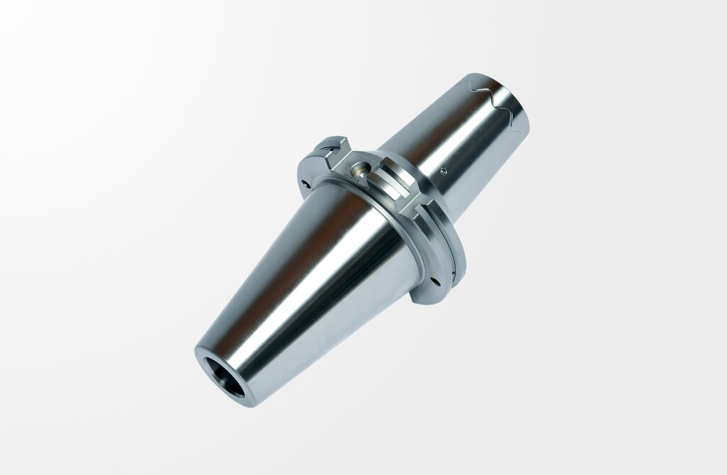
The Power Shrink Chuck is the shrink fit chuck for highest machining capacity in high-speed manufacturing. The optimized design combines high rigidity with dampening vibrations, therefore giving more protection to machines, spindles and tools.

Description
Power Shrink Chuck, DIN ISO 7388-1, SK50
(formerly DIN 69871)
Quality pass
Chuck fine balanced G2.5 at 25.000 rpm
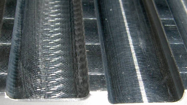
All functional surfaces fine machined
Taper tolerance AT3
Coolant supply form AD/AF
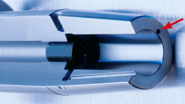
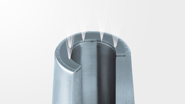
Cool Jet, can be sealed
- Increased machining capacity due to higher spindle speed, higher feed and larger cutting depth
- Shorter processing times
- Quieter running, therefore better surface quality and protection of tools, spindles and machines
- Higher machining accuracy
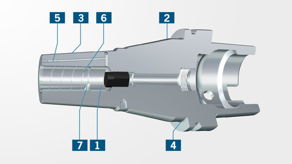
- With threaded holes in order to balance with balancing screws
- Cool Jet bores that can be sealed included
- High rigidity
- Slim at the tip
- Dampen vibrations
- High clamping force
- Equally suited to high-speed manufacturing and heavy milling
- Universal usage, saves space in tool magazine
Scope of Delivery
- With backup screw
HAIMER TIP
For RPM higher 8000 U/min we recommend the optional cooling system Cool Flash. (on request)
Technical specifications

Notice
Technical data subjects to change without prior notice.
| Description | Norm: Haimer | Value: metric/inch |
|---|---|---|
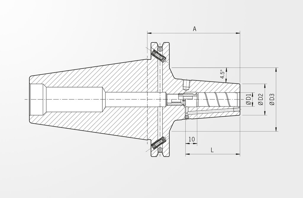
| Clamping diameter | D1 | 6 inch / 0.236 inch |
| Length A | A | 160 inch / 6.299 inch |
| A-length version | überlang (160 mm) | |
| Diameter 2 | D2 | 21 inch / 0.827 inch |
| Diameter 3 | D3 | 78 inch / 3.071 inch |
| Length | L | 36 inch / 1.417 inch |
| Interface | SK50 | |
| Upgrade | mit Cool Jet |
| Description | Norm: DIN 4000 | Value: metric/inch |
|---|---|---|
| Mass (weight) | D7 | 4,718 kg |
| Standard number of properties layout | NSM | DIN4000-89 |
| Flange diameter | A4 | 97,5 inch / 3.839 inch |
| item style code | BLDf | 1 |
| item style code | BLD | 508145 |
| Connection code type machine side | C11 | SKG |
| Connection code form type machine side | C12 | 17 |
| Connection thread nominal size machine side | C13 | M24 |
| Connection code unit base machine side | C14 | 9 |
| Connection code style machine side | C15 | 5 |
| Connection size code machine side | C2 | 0500 |
| Connection code type workpiece side | C51 | ZYL |
| Connection code form type workpiece side | C52 | 10 |
| Connection code unit base workpiece side | C54 | 1 |
| Connection code style workpiece side | C55 | 5 |
| Hand | E1 | N |
| coolant exit style code | H22 | 3 |
| Company identification | J3 | HAI |
| interface code to workpiece side | J4 | ZYL00600115 |
| interface code to machine side | J6 | SKG05001795 |
| Description | Norm: ISO 13399 | Value: metric/inch |
|---|---|---|
| Weight | WT | 4,718 kg |
| Standard number of properties layout | NSM | DIN4000-89 |
| Flange diameter | DF | 97,5 inch / 3.839 inch |
| Connection code type machine side | CCTMS | SKG |
| Connection code unit base workpiece side | CCUWS | 1 |
| Connection code style workpiece side | CCSWS | 5 |
| Hand | HAND | N |
| coolant exit style code | CXSC | 3 |
| Company identification | COMPC | HAI |