Shrink fit chuck suitable to all kind of shrink fit units.
JIS B 6339-2 BT40 form JD/JF.
Form JD/JF means: Form JD/JF: interior coolant supply through centre (Form JD) and through the collar (form JF)

Description
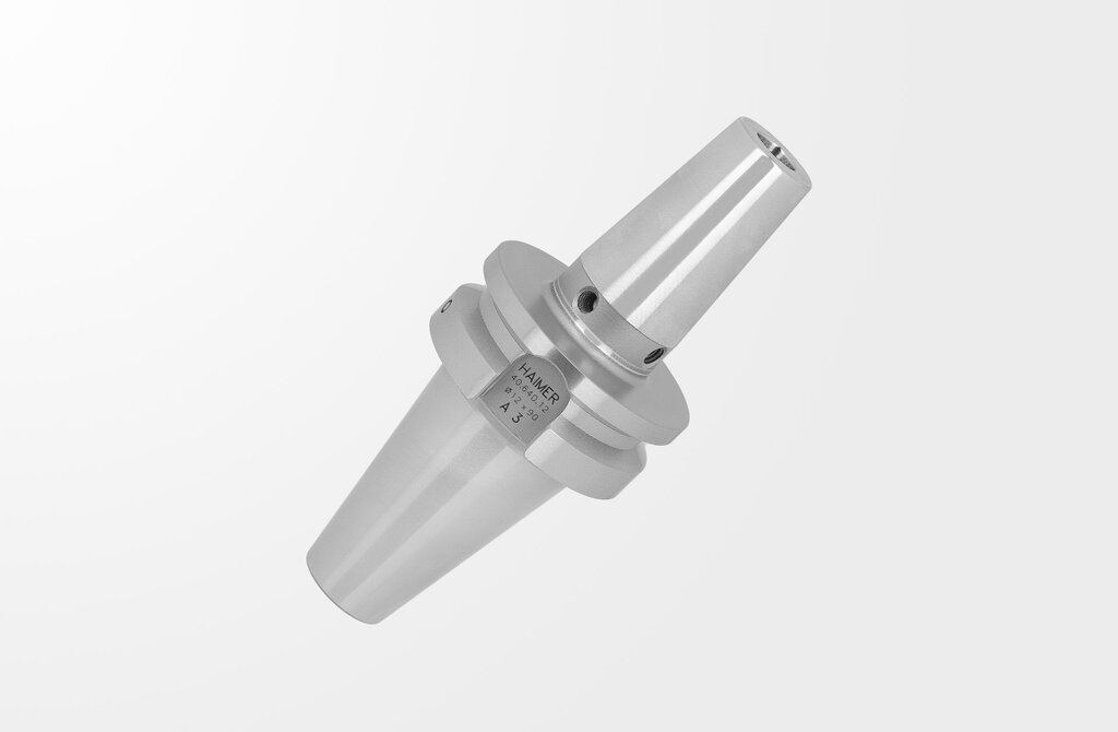
Shrink Fit Chuck Standard Version, JIS B 6339-2, BT40
Quality pass
Chuck body fine balanced G2.5 at 25.000 rpm or U < 1 gmm
All functional surfaces fine machined
Taper tolerance AT3
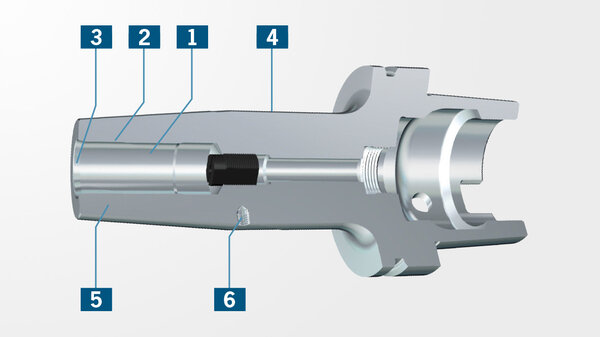
Coolant supply form JD/JF
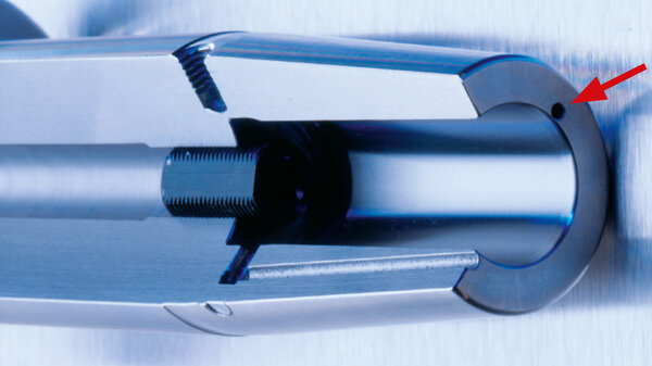
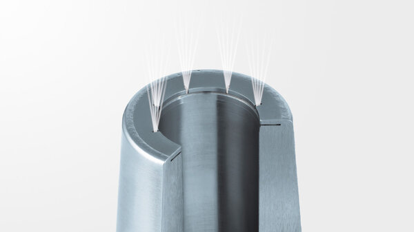
Cool Jet, can be sealed
- Heat resistant hot-working steel
- Hardened 54 – 2 HRC
- For HSS and solid carbide tools
- Shank tolerance h6
- With threaded holes in order to balance with balancing screws
Scope of Delivery
- With backup screw
HAIMER TIP
For a constant and acurate cooling of te cutting tool we recommend the optional cooling system Cool Jet.
For RPM higher 8000 U/min we recommend the optional cooling system Cool Flash. (on request)
Technical specifications

Notice
Technical data subjects to change without prior notice.
| Description | Norm: Haimer | Value: metric/inch |
|---|---|---|
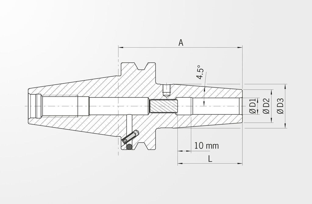
| Clamping diameter | D1 | 6,35 inch / 1/4 inch |
| Length A | A | 90 inch / 3.543 inch |
| A-length version | kurz | |
| Diameter 2 | D2 | 21 inch / 0.827 inch |
| Diameter 3 | D3 | 27 inch / 1.063 inch |
| Length | L | 36 inch / 1.417 inch |
| Interface | BT40 | |
| Upgrade | mit Cool Jet |
| Description | Norm: DIN 4000 | Value: metric/inch |
|---|---|---|
| Mass (weight) | D7 | 1,277 kg |
| Standard number of properties layout | NSM | DIN4000-89 |
| Body diameter 1 | A1 | 27 inch / 1.063 inch |
| Flange diameter | A4 | 63 inch / 2.48 inch |
| Interference diameter | A6 | 21 inch / 0.827 inch |
| Length body diameter 1 | B1 | 63 inch / 2.48 inch |
| Protruding length | B3 | 90 inch / 3.543 inch |
| Overall length | B4 | 155,4 inch / 6.118 inch |
| Taper angle | B51 | 4,5 ° |
| item style code | BLD | 508145 |
| Connection code type machine side | C11 | SKG |
| Connection code form type machine side | C12 | 57 |
| Connection code unit base machine side | C14 | 9 |
| Connection code style machine side | C15 | 5 |
| Connection size code machine side | C2 | 0400 |
| Connection code type workpiece side | C51 | ZYL |
| Connection code form type workpiece side | C52 | 01 |
| Connection code unit base workpiece side | C54 | 3 |
| Connection code style workpiece side | C55 | 5 |
| Connection size code workpiece side | C6 | 0250 |
| Connection diameter min | C71 | 6,35 |
| Clamping length max. / nominal length | C81 | 36 inch / 1.417 inch |
| Clamping length, min., workpiece side | C82 | 26 inch / 1.024 inch |
| Balance grade | D5 | G2,5/25000 |
| Rotation speed, max | D6 | 25000 |
| Balancing device | D51 | 1 |
| Hand | E1 | N |
| coolant entry style code | H21 | 7 |
| coolant exit style code | H22 | 3 |
| Company identification | J3 | HAI |
| interface code to workpiece side | J4 | ZYL02500135 |
| interface code to machine side | J6 | SKG04005795 |
| Description | Norm: ISO 13399 | Value: metric/inch |
|---|---|---|
| Weight | WT | 1,277 kg |
| Standard number of properties layout | NSM | DIN4000-89 |
| Body diameter 1 | BD1 | 27 inch / 1.063 inch |
| Flange diameter | DF | 63 inch / 2.48 inch |
| Interference diameter | DCINTF | 21 inch / 0.827 inch |
| Length body diameter 1 | LBD1 | 63 inch / 2.48 inch |
| Protruding length | LPR | 90 inch / 3.543 inch |
| Overall length | OAL | 155,4 inch / 6.118 inch |
| Taper angle | TA | 4,5 ° |
| Connection code type machine side | CCTMS | SKG |
| Connection code unit base workpiece side | CCUWS | 3 |
| Connection code style workpiece side | CCSWS | 5 |
| Connection size code workpiece side | CZCWS | 0250 |
| Connection diameter min | DCONN | 6,35 |
| Clamping length max. / nominal length | LSCX | 36 inch / 1.417 inch |
| Hand | HAND | N |
| coolant entry style code | CNSC | 7 |
| coolant exit style code | CXSC | 3 |
| Company identification | COMPC | HAI |