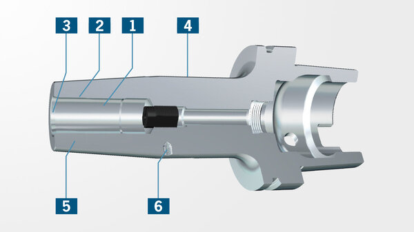
Shrink fit chuck for clamping shank tools, suitable for use with all available shrink fit units.
With steep taper SK40 form AD/AF DIN ISO 7388-1 (formerly DIN 69871) and Shrink Fit version similar to DIN 69882-8. Form AD/AF means: Central coolant supply and coolant channels through the flange which can be sealed again.


Description
Shrink Fit Chuck Standard Version with Cool Jet, DIN ISO 7388-1, SK40
(formerly DIN 69871)
Quality pass
Chuck fine balanced G2.5 at 25.000 rpm or U < 1 gmm
All functional surfaces fine machined
Taper tolerance AT3
Coolant supply form AD/AF
- Heat resistant hot-working steel
- Hardened 54 – 2 HRC
- For HSS and solid carbide tools
- Shank tolerance h6
- With threaded holes in order to balance with balancing screws
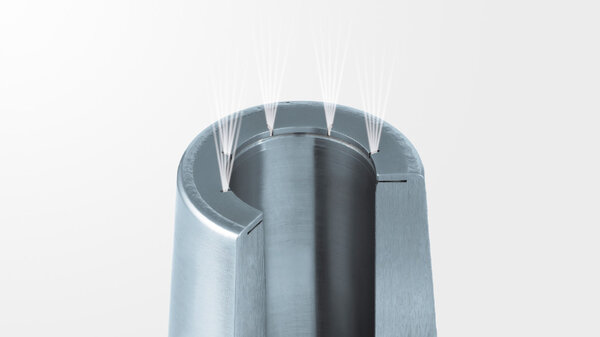
- Cool Jet coolant bores included (for Ø6-32 mm) or with slits along the clamping bore for cooling from outside (for Ø3-5 mm)
Scope of Delivery
- With backup screw
HAIMER TIP
For rpm higher than e.g. 8000 we recommend the optional cooling system Cool Flash. (on request)

Technical specifications
Notice
Technical data subjects to change without prior notice.
| Description | Norm: Haimer | Value: metric/inch |
|---|---|---|
| Clamping diameter | D1 | 14 inch / 0.551 inch |
| Length A | A | 80 inch / 3.15 inch |
| A-length version | kurz | |
| Diameter 2 | D2 | 27 inch / 1.063 inch |
| Diameter 3 | D3 | 34 inch / 1.339 inch |
| Interface | SK40 | |
| Upgrade | mit Cool Jet | |
| Clamping length | L | 47 inch / 1.85 inch |
| Description | Norm: DIN 4000 | Value: metric/inch |
|---|---|---|
| Mass (weight) | D7 | 1,120 kg |
| Standard number of properties layout | NSM | DIN4000-89 |
| Body diameter 1 | A1 | 34 inch / 1.339 inch |
| Flange diameter | A4 | 63,55 inch / 2.502 inch |
| Interference diameter | A6 | 27 inch / 1.063 inch |
| Length body diameter 1 | B1 | 60,9 inch / 2.398 inch |
| Protruding length | B3 | 80 inch / 3.15 inch |
| Overall length | B4 | 148,4 inch / 5.843 inch |
| Taper angle | B51 | 4,5 ° |
| Functional length | B71 | 33 inch / 1.299 inch |
| item style code | BLD | 508145 |
| Connection code type machine side | C11 | SKG |
| Connection code form type machine side | C12 | 17 |
| Connection thread nominal size machine side | C13 | M16 |
| Connection code unit base machine side | C14 | 9 |
| Connection code style machine side | C15 | 5 |
| Connection size code machine side | C2 | 0400 |
| Connection code type workpiece side | C51 | ZYL |
| Connection code form type workpiece side | C52 | 01 |
| Connection code unit base workpiece side | C54 | 1 |
| Connection code style workpiece side | C55 | 5 |
| Connection size code workpiece side | C6 | 0140 |
| Connection diameter min | C71 | 14 |
| Clamping length max. / nominal length | C81 | 47 inch / 1.85 inch |
| Clamping length, min., workpiece side | C82 | 37 inch / 1.457 inch |
| Balance grade | D5 | G2,5/25000 |
| Rotation speed, max | D6 | 25000 |
| Balancing device | D51 | 1 |
| Hand | E1 | N |
| coolant entry style code | H21 | 7 |
| coolant exit style code | H22 | 3 |
| Company identification | J3 | HAI |
| interface code to workpiece side | J4 | ZYL01400115 |
| interface code to machine side | J6 | SKG04001795 |
| Description | Norm: ISO 13399 | Value: metric/inch |
|---|---|---|
| Weight | WT | 1,120 kg |
| Standard number of properties layout | NSM | DIN4000-89 |
| Body diameter 1 | BD1 | 34 inch / 1.339 inch |
| Flange diameter | DF | 63,55 inch / 2.502 inch |
| Interference diameter | DCINTF | 27 inch / 1.063 inch |
| Length body diameter 1 | LBD1 | 60,9 inch / 2.398 inch |
| Protruding length | LPR | 80 inch / 3.15 inch |
| Overall length | OAL | 148,4 inch / 5.843 inch |
| Taper angle | TA | 4,5 ° |
| Functional length | LF | 33 inch / 1.299 inch |
| Connection code type machine side | CCTMS | SKG |
| Connection code unit base workpiece side | CCUWS | 1 |
| Connection code style workpiece side | CCSWS | 5 |
| Connection size code workpiece side | CZCWS | 0140 |
| Connection diameter min | DCONN | 14 |
| Clamping length max. / nominal length | LSCX | 47 inch / 1.85 inch |
| Hand | HAND | N |
| coolant entry style code | CNSC | 7 |
| coolant exit style code | CXSC | 3 |
| Company identification | COMPC | HAI |